Mobility is one of the key aspects in the mobile telecom networks.


We would like to travel with our phones and has a continuous access to the used service. Moving around the city while still talking to your friend is what we need, want and expect from the mobile network.
The phone measures the strength and quality of the radio signal received from the base station. Information about what exactly shall be measured is sent from the gNB to the UE using RRC protocol.
Sometimes it may happen that the phone will find the cell that it was not supposed to find. In such case the phone will report this new "unknown" cell to the gNB. When several phones do the same the gNB may decide to add this "unknown" cell as a known neighbor cell and next time the gNB will tell other devices to actually measure radio signal for this particular cell. This is part of SON functionality called ANR.
Measurements
There is couple defined Measurement Events. Definitions for those are gathered in Table 1.
| Name | Description |
|---|---|
| Event A1 | Serving becomes better than threshold |
| Event A2 | Serving becomes worse than threshold |
| Event A3 | Neighbor becomes offset better than SpCell |
| Event A4 | Neighbor becomes better than threshold |
| Event A5 | SpCell becomes worse than threshold1 and neighbor becomes better than threshold2 |
| Event A6 | Neighbour becomes offset better than SCell |
| Event B1 | Inter RAT neighbour becomes better than threshold |
| Event B2 | PCell becomes worse than threshold1 and inter RAT neighbor becomes better than threshold2 |
But what does that mean?
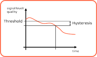
The phone is connected to one specific cell, it actually could be more cells but there is always one that is the anchor cell and through which the phone talks to the network. This cell is known as Serving Cell or SpCell (Special Purpose Cell). When network would like to know when the strenght/quality of the radio signal is bad then it will tell the phone to report this situation using Event A2 (Figure 1).
Figure 1 Simplfied Event A2 illustration.
Handovers
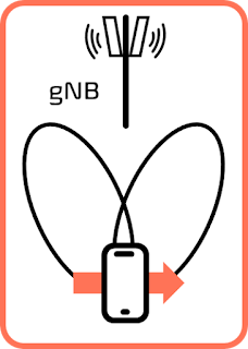
There are number of types of handovers. The phone may change the cell within one gNB and this will be called intra-gNB handover (Figure 2), but it may also move from a cell within gNB to the cell that belongs to another gNB. This latter case is known as inter-gNB handover (Figure 3).

Figure 2 Ilustration of intra-gNB handover

Figure 3 Illustration of inter-gNB handover.
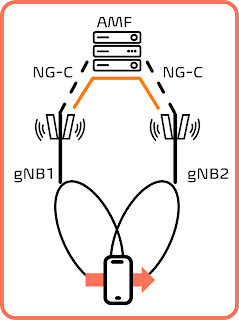
Figure 3 depicts the handover between two base stations when those are interconnected with interface called Xn. That is why this type of handover is often refered as Xn hanodover. This interface however is optional and thus another interface shall be used. Each gNB is connected to the core network and in particular to the AMF. Interface between the gNB and the AMF is called NG. Handover performed with assistance from the AMF is known as NG based handover. It is also inter-gNB handover. This is depicted in Figure 4.

Figure 4 Inter-gNB NG based handover.
The mobile network is usually deployed using not one but couple different frequency bands. That is why in this domain intra- and inter-frequency handover are named.
All of those handovers above are done within the NR system and because of the could be called intra-system ones.
Should it be possible to do the handover between NR and LTE, well, absolutely! Those are called inter-system handovers. In the example depicted in Figure 5 the mobile changes the system and also Radio Access Technology, thus this handover might be also called inter-RAT handover or in short IRAT.

Figure 5 Illustration of inter-system handover
It shall be mentioned that not all IRAT handovers are inter-system handovers in the 5G networks.
The eNB (LTE node) might be connected to 5GC. Such eNB is called ng-eNB.
I think I should also remind that there are two duplex mode available in the NR i.e. FDD and TDD. Shall it be possible to the handover between two cells using two different duplex modes? Well, Yes! Those handovers are called sometimes inter-mode ones.
Comments
Post a Comment